Where it stands
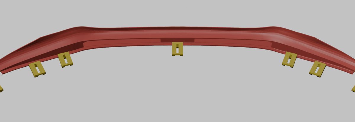
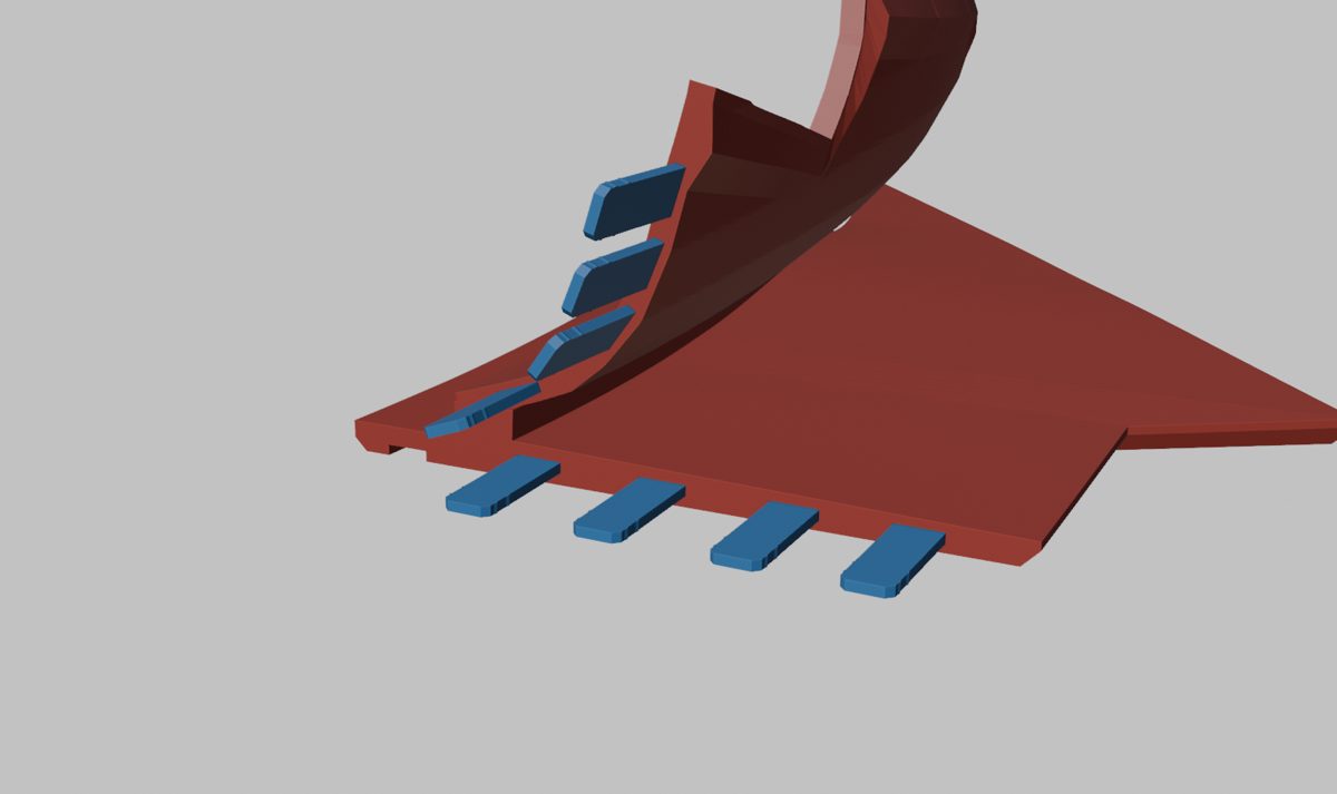
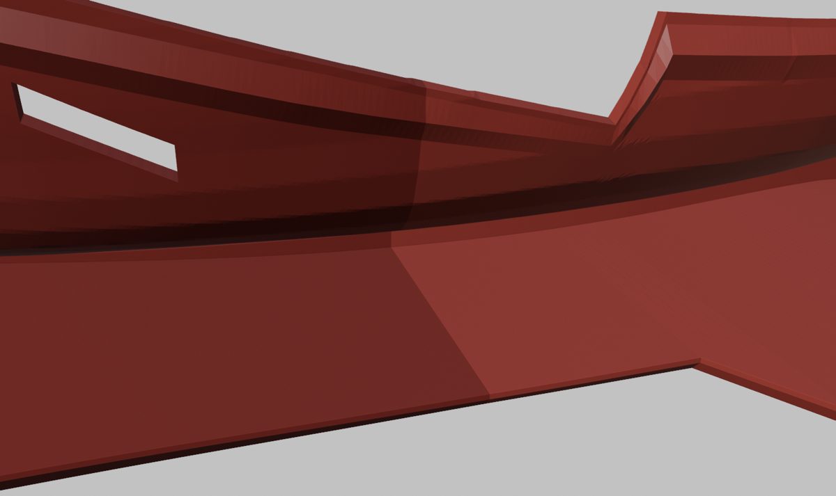
The lip is drawn, cut into printable sections and sliced. One corner has been test-printed. That print failed at the mounting clips, so the mount has been redesigned and the new version hasn't been printed yet. Nothing on this page has been fitted to the car in its current form. The pictures are design renders with the lip in red so the parts are easy to tell apart; the real one will be black.
The shape
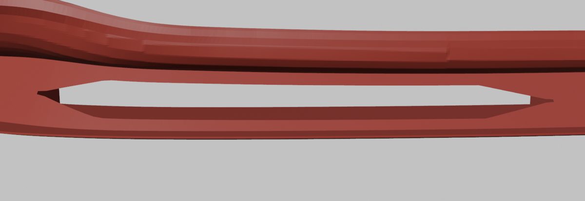
It runs about 1,880 mm, from one wheel arch round the nose to the other. The middle is 1,500 mm wide with a scoop opening each side of centre, and each corner wraps the last stretch of the bumper to the arch. The middle tapers to a point at each end and lies over the corner piece, so there's no blunt end face on show where they meet.
Eleven pieces
The printer's bed is 256 mm, so the lip is cut into eleven sections: seven across the middle and two for each corner.
| Section | How many | On the bed | Height |
|---|---|---|---|
| Middle, centre | 1 | 203 × 203 mm | 62 mm |
| Middle, first out from centre | 2 | 203 × 202 mm | 68 mm |
| Middle, second out | 2 | 202 × 202 mm | 87 mm |
| Middle, ends | 2 | 220 × 220 mm | 84 mm |
| Corner, inner half | 2 | 172 × 172 mm | 65 mm |
| Corner, outer half | 2 | 195 × 194 mm | 120 mm |
One complete corner, both halves plus its hardware on a single plate, sliced at 278 g and 9 hours 23 minutes.
The mount: no drilling
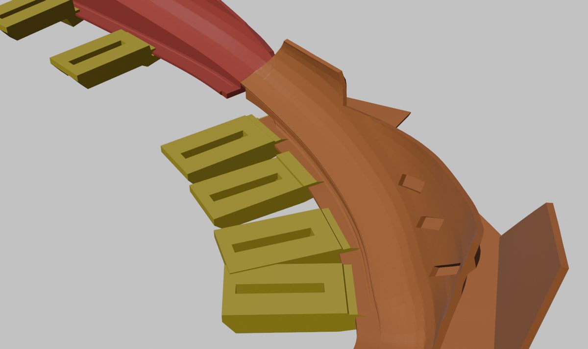
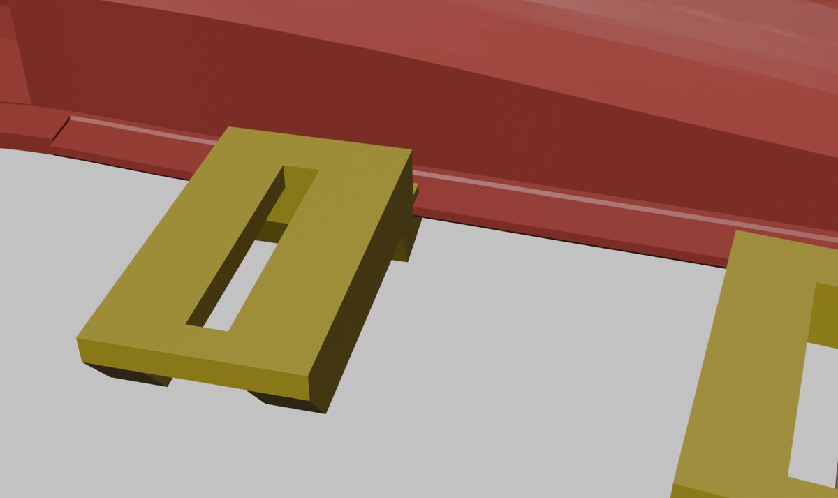
Most lips screw straight up into the bumper, which means new holes in the car. This one doesn't. A dovetail groove runs along the back edge of the lip, with a row of small teeth in it. Brackets slide along that groove to wherever the car's own undertray screws are, lock onto the teeth, and a slotted arm on each bracket goes under the factory screw.
Because the brackets slide, the lip doesn't have to know exactly where each screw is. The brackets come in six heights, from 4.5 to 24 mm, to make up the gap between the lip and the bumper at each spot. The plan is four per corner, two each side of the middle and one at the centre.
The first test print failed
The first corner came off the printer on November 12 and didn't survive being put together. The clips used a thin spring finger to hold themselves on the rail, and the fingers snapped. The clips sat loose, the two halves of the corner lifted apart, and the joint between them had play.
That's what a test print is for. Two things changed the same day:
- The spring finger is gone. A thin printed finger that has to flex every time is the wrong idea for this job. The bracket now locks solidly onto the rail teeth instead of springing onto them.
- The corner joint was redone. The two halves now meet on plain cut faces with eight flat pegs hidden inside the seam, each one reaching 18 mm into both halves.
A seam that doesn't show
The earlier corner joint used dovetails you could see from outside, and they broke up the lines of the lip. With the pegs buried in the seam, the closed joint is a single hairline.
Plastic
Test pieces are printed in PLA because it's quick and cheap for checking fit, and that's all it's for. PLA softens in a hot car park, so the lip that goes on the road gets printed in PETG or ASA, and so do the brackets. There's more on that in which plastic survives a hot car.
What's next
- Print the redesigned corner and check the new brackets and the pegged joint.
- Fit it to the car and correct the bracket positions against the real screws.
- Print the middle sections and fit the whole lip.
- Heat and road time before anyone else gets one.
This page gets updated as each step happens. For the general version of how a lip gets printed in sections, see can you 3D print a front lip?