What goes in it
The layout here is the one the enclosure in the shop is drilled for: 8 push buttons, 3 toggle switches and 2 rotary encoders. It's a good size for most cars, with enough for the things you change mid-race and nothing you'll forget about.
| Part | What to buy | Use it for |
|---|---|---|
| Push buttons ×8 | 16 mm momentary, normally open | Pit limiter, headlights flash, wipers, radio, look back, reset |
| Toggles ×3 | 6 mm mini toggles (MTS-102 type) | Ignition, starter, headlights on/off |
| Rotary encoders ×2 | EC11 with push switch, 6 mm D-shaft | Brake bias, traction control, ABS, black box scroll |
| Board | Arduino Pro Micro (ATmega32U4), or a ready-made USB encoder board | Turns the switches into a USB game controller |
| Wire | 22–26 AWG stranded, a few colours | Easier to trace when something doesn't work |
Pro Micro or a plug-and-play board?
Arduino Pro Micro. A few dollars, and because the ATmega32U4 chip handles USB itself, Windows sees it as a game controller once it's flashed with a joystick sketch (the Arduino Joystick library is the common one). You need to upload code once. Get the 32U4 version; the cheaper boards with a different chip can't act as a controller.
Ready-made USB encoder board (Leo Bodnar BU0836 and similar). Wire the switches to the terminals and plug it in. No code, very reliable, costs a lot more. Worth it if you never want to open the Arduino IDE.
Wiring: you don't need a matrix
Most guides go straight to a button matrix with a diode on every switch. That's for boxes with 30 or more controls. A Pro Micro has 18 usable input pins, and this layout needs 17:
- 8 buttons: 1 pin each = 8
- 3 toggles: 1 pin each = 3
- 2 encoders: 2 pins for the rotation and 1 for the push click = 6
Wire one leg of every switch to its own pin and the other leg to a shared ground. In the sketch, set each pin to INPUT_PULLUP so it reads high until the switch connects it to ground. No resistors, no diodes. If you ever add more controls than you have pins, that's when to build a matrix. The wiring guide has the pin table and the full sketch.
Encoders need a little code: each click one way sends a short press of one button, each click the other way sends another. Most joystick sketches for button boxes already include this, and games treat it as two buttons (bias up, bias down).
Putting it together
- Fit the buttons, toggles and encoders to the front panel and tighten the nuts. The anti-rotation holes keep the toggles from twisting.
- Run the ground wire around the panel from switch to switch first, then one signal wire from each switch to the board.
- Label the board end of each wire, or keep a note of which pin is which control.
- Flash the board, plug it in and check every switch in Windows' game controller settings (search for "Set up USB game controllers") before closing the lid.
- Screw the lid on, route the USB cable out the back and bolt the box to the rig.
Setting it up in the sim
iRacing, ACC, Automobilista 2 and the rest all see it as one more controller. Open the controls menu, click the function you want, press the button on the box. Do it once per sim. Save the button layout somewhere, since a Windows update can occasionally shuffle controller IDs.
The enclosure
The box is the part most people improvise with a project box and a drill, and the holes end up crooked. The enclosure here comes drilled for this exact layout, with a 3.5 mm front panel, heat-set inserts for the lid screws and slots to bolt straight onto 40-series profile.
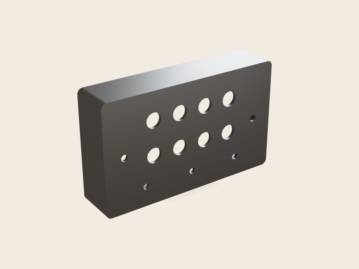 Sim racingSim-racing button box enclosureFits 16 mm push buttons, 6 mm mini toggles (MTS type), EC11 rotary encoders; 40-series rig profile
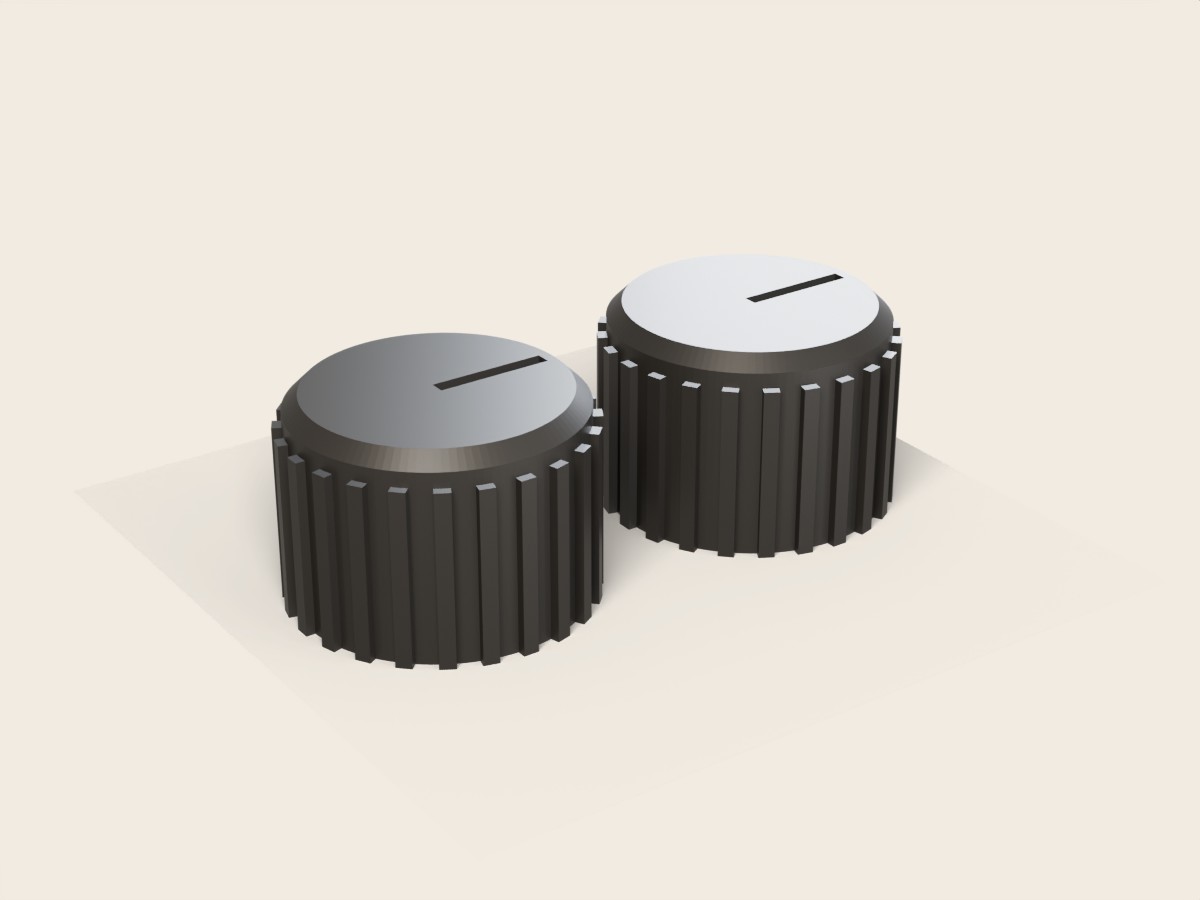 Sim racingRotary encoder knobs, pairFits 6 mm D-shaft (EC11 encoders and most panel pots)
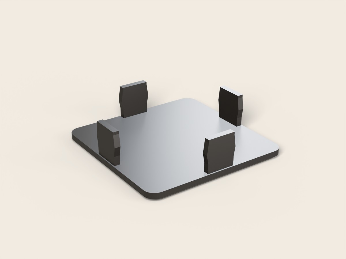 Sim racing40-series profile end caps, 4 packFits 40 x 40 profile with 8 mm slots (40 x 80 version on request)
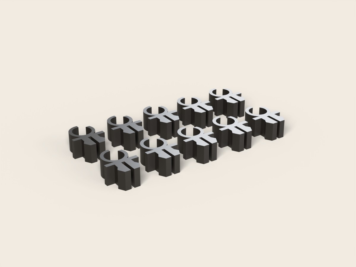 Sim racingRig profile cable clips, 10 packFits 8 mm slot profile; cables or bundles up to 8 mm