The rule that covers every switch
Every control in the box is wired the same way: one leg to its own pin on the board, the other leg to ground. That's it. The board's built-in pull-up resistor holds each pin high, and closing the switch pulls it to ground, which the sketch reads as "pressed". There are no resistors to add and no diodes, because nothing shares a pin.
This works for the layout in the build guide (8 push buttons, 3 toggles, 2 encoders with push switches), which needs 17 pins. A Pro Micro has 18 you can use.
Run the ground first
Solder one long ground wire that visits every switch in a chain: button to button along the top row, down to the toggles, across to the encoders. One end of that chain goes to a GND pin on the board. Doing the ground as one daisy chain means only one wire per control has to travel back to the board, and the inside of the box stays readable.
- Push buttons: two legs, no polarity. Either leg can be the ground one.
- Toggles (MTS-102, three legs): use the middle leg and one outer leg. Leave the third leg empty.
- EC11 encoders: the side with three pins is the rotation: the middle pin is ground, the outer two are A and B. The side with two pins is the push switch: one to ground, one to a pin.
Pin table
These are the pin labels printed on a Pro Micro. The "shows up as" column is the button number Windows and the sim will see.
| Control | Board pin | Shows up as |
|---|---|---|
| Push buttons 1 to 8 | 2, 3, 4, 5, 6, 7, 8, 9 | Buttons 1 to 8 |
| Toggles 1 to 3 | 10, 16, 14 | Buttons 9 to 11 |
| Encoder 1 push | 15 | Button 12 |
| Encoder 2 push | A0 | Button 13 |
| Encoder 1 rotation (A, B) | A1, A2 | Buttons 14 and 15 (one per direction) |
| Encoder 2 rotation (A, B) | 1 (TX), 0 (RX) | Buttons 16 and 17 (one per direction) |
| Spare | A3 | Room for one more button |
| Ground chain | GND |
If an encoder counts backwards when you're done (bias goes up when you turn it down), swap its A and B wires, or swap the two assignments in the sim. Nothing is damaged either way.
The sketch
Install the Arduino IDE, then add the Arduino Joystick Library by Matthew Heironimus (download the ZIP from its GitHub page, then Sketch > Include Library > Add .ZIP Library). Pick Arduino Leonardo as the board, since a Pro Micro uses the same chip, paste this in and upload.
#include <Joystick.h>

// 8 buttons, 3 toggles, 2 encoder pushes
const byte SW[13] = {2, 3, 4, 5, 6, 7, 8, 9,  10, 16, 14,  15, A0};
// encoder rotation pins: {A, B}
const byte ENC[2][2] = {{A1, A2}, {1, 0}};

Joystick_ Joystick(JOYSTICK_DEFAULT_REPORT_ID, JOYSTICK_TYPE_GAMEPAD,
  17, 0, false, false, false, false, false, false,
  false, false, false, false, false);

byte lastA[2];
unsigned long pulseEnd[4];

void setup() {
  for (byte i = 0; i < 13; i++) pinMode(SW[i], INPUT_PULLUP);
  for (byte e = 0; e < 2; e++) {
    pinMode(ENC[e][0], INPUT_PULLUP);
    pinMode(ENC[e][1], INPUT_PULLUP);
    lastA[e] = digitalRead(ENC[e][0]);
  }
  Joystick.begin();
}

void loop() {
  // switches: pressed = pin pulled to ground
  for (byte i = 0; i < 13; i++)
    Joystick.setButton(i, !digitalRead(SW[i]));

  // encoders: each click sends a short press of one of two buttons
  for (byte e = 0; e < 2; e++) {
    byte a = digitalRead(ENC[e][0]);
    if (a != lastA[e]) {
      lastA[e] = a;
      if (a == LOW) {
        byte dir = digitalRead(ENC[e][1]) == HIGH ? 0 : 1;
        byte k = e * 2 + dir;
        Joystick.setButton(13 + k, 1);
        pulseEnd[k] = millis() + 40;
      }
    }
  }
  for (byte k = 0; k < 4; k++) {
    if (pulseEnd[k] && millis() > pulseEnd[k]) {
      Joystick.setButton(13 + k, 0);
      pulseEnd[k] = 0;
    }
  }
  delay(1);
}
The 40 in pulseEnd[k] = millis() + 40 is how long each encoder click holds its button, in milliseconds. If a sim misses clicks when you spin the knob fast, raise it to 60.
Test before the lid goes on
Plug the box in, press the Windows key, type Set up USB game controllers and open the board's properties. You get a grid of numbered lights. Press each control and check it against the table above. Spin each encoder both ways: two different lights should blink.
When a switch does nothing
| What you see | Usual cause |
|---|---|
| One button dead | Its signal wire is on the wrong pin or the joint is cold. Reheat both ends. |
| A whole row dead | The ground chain is broken just before the first dead switch. |
| A button always on | Its signal wire is touching ground, often a stray strand at the board. |
| Toggle dead in one position | That's normal: an on-off toggle only connects in one position. |
| Encoder only goes one way | Either A or B isn't connected, or the middle pin isn't on ground. |
| Encoder skips or doubles | Raise the 40 ms pulse, and keep its wires short and away from the USB cable. |
| Windows doesn't see a controller | The board isn't a 32U4, or the cable is charge-only. Try another cable first. |
Toggles in iRacing and ACC
A toggle holds its button down for as long as it's on. That suits headlights in some sims, but ignition and starter usually want a press, so the car only reacts when you flip the toggle one way. Two fixes: map toggles to functions that accept a held input, or use spring-return (momentary) toggles for ignition and starter, which behave like buttons and still look right.
The box it goes in
The enclosure in the shop is drilled for exactly this layout, so the pin table above matches it hole for hole. The Pro Micro sits inside the back lid next to the USB cable exit.
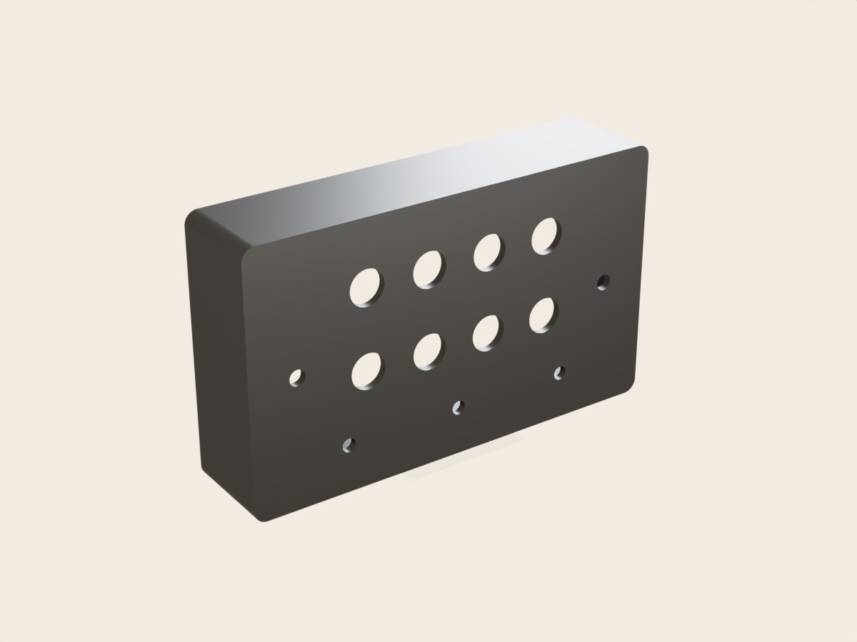 Sim racingSim-racing button box enclosureFits 16 mm push buttons, 6 mm mini toggles (MTS type), EC11 rotary encoders; 40-series rig profile
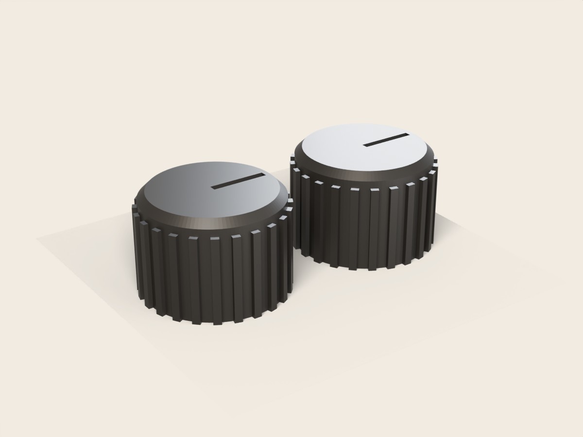 Sim racingRotary encoder knobs, pairFits 6 mm D-shaft (EC11 encoders and most panel pots)
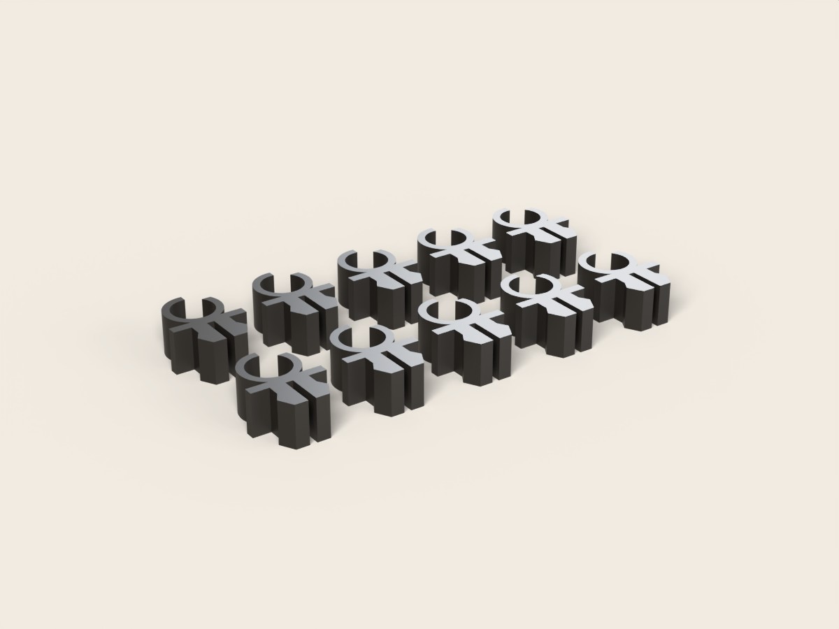 Sim racingRig profile cable clips, 10 packFits 8 mm slot profile; cables or bundles up to 8 mm